Reviving "Borkin" Power On/Off Button for the Raspberry Pi 4B
13/04/2020 - 13:37 by poneyThere are some resources explaining how to leverage the jack audio port from the Raspberry Pi 2, 3 and 3B+ to make a neat and nice power on/off button. However this doesn't work for the Raspberry Pi 4B.
This post explains the general concept behind it, why it doesn't work on RPi4B and how to revive it.
How can we make a power on/off button?
According to BCM2711 bootloader config documentation, if WAKE_ON_GPIO is set to 1, then powering off a Raspberry Pi leads to switching it to a low power mode. It can then wake up by grounding GPIO3 or GLOBAL_EN. This same port can be leveraged to implement the shutdown process as well.
This can be acheived in 2 ways:
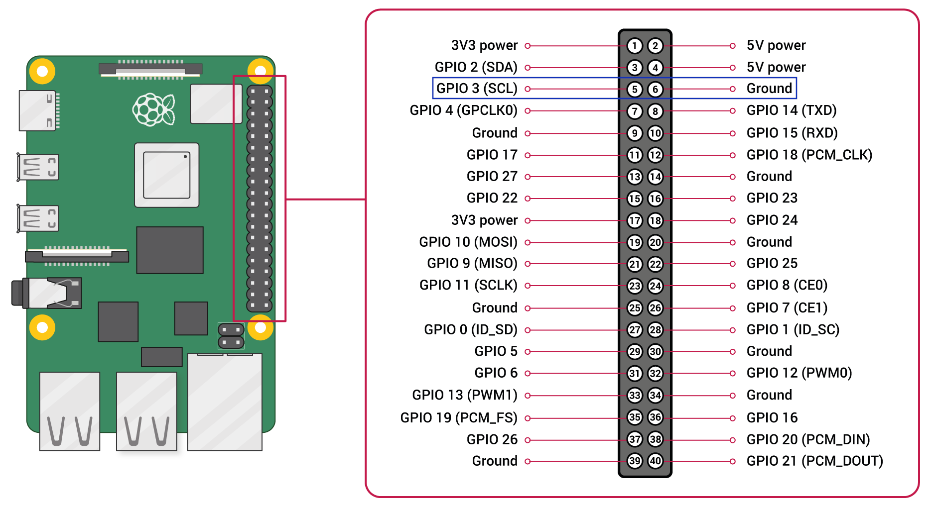
- wire GPIO3 (Pin#5) and any ground GPIO (eg. Pin#6) to a push-button (example)
- wire GPIO3 to an existing port. That's exactly what the Borkin button does by repurposing one of the Jack Socket (example 2).
Here is a view of the Raspberry Pi GPIOs:
How to leverage the A/V Jack Socket for a power on/off button?
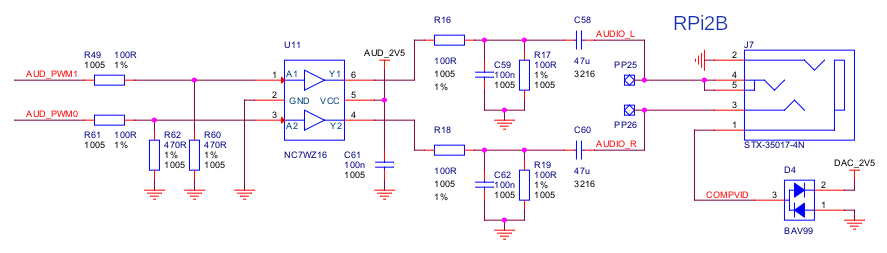
From the official schematics, we can see the following wiring for A/V Jack port:
RPi2 rev 1.2:
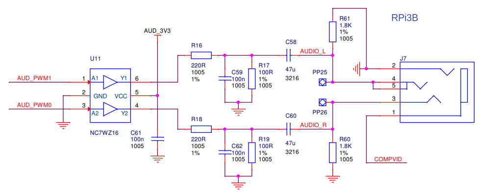
RPi3B rev 1.2:
RPi3B+ rev. 1.0:

RPi4B 4.0:
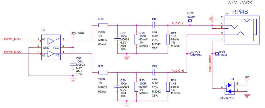
From these schematics, it's possible to highlight two important bands #1 and #2 (GND). The #1 can be a good candidate to get wired with GPIO3.
Mapping these schematics to their implementation, shows that the Raspberry Pi board is using the 3.5mm 4 Pole Jack Sockets from CLIFF (FC68125):

Using a multimeter, these ports can be mapped to the following pins on the RPi4B:
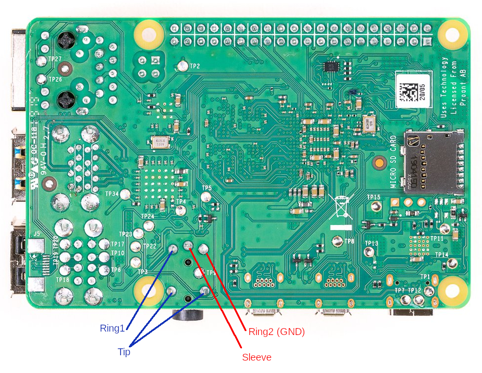
Can we make or reuse an existing technology to make a push button connecting Sleeve (band #1) and Ring2 (band #2)? The answser is yes, there are some "click 3.5mm jack buttons" sold for around 1 USD online. Pressing the button will connect the two pointed parts, which is exactly what is looked for here.

This has been proven to be working on the RPi2, 3B and 3B+, but doesn't work on the RPi4B, where the documented A/V schematics are exactly the same.
Why doesn't it work on the RPi4?
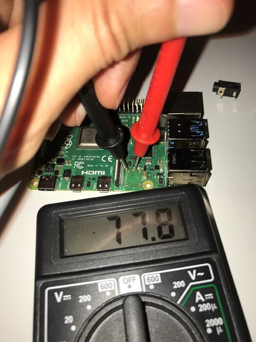
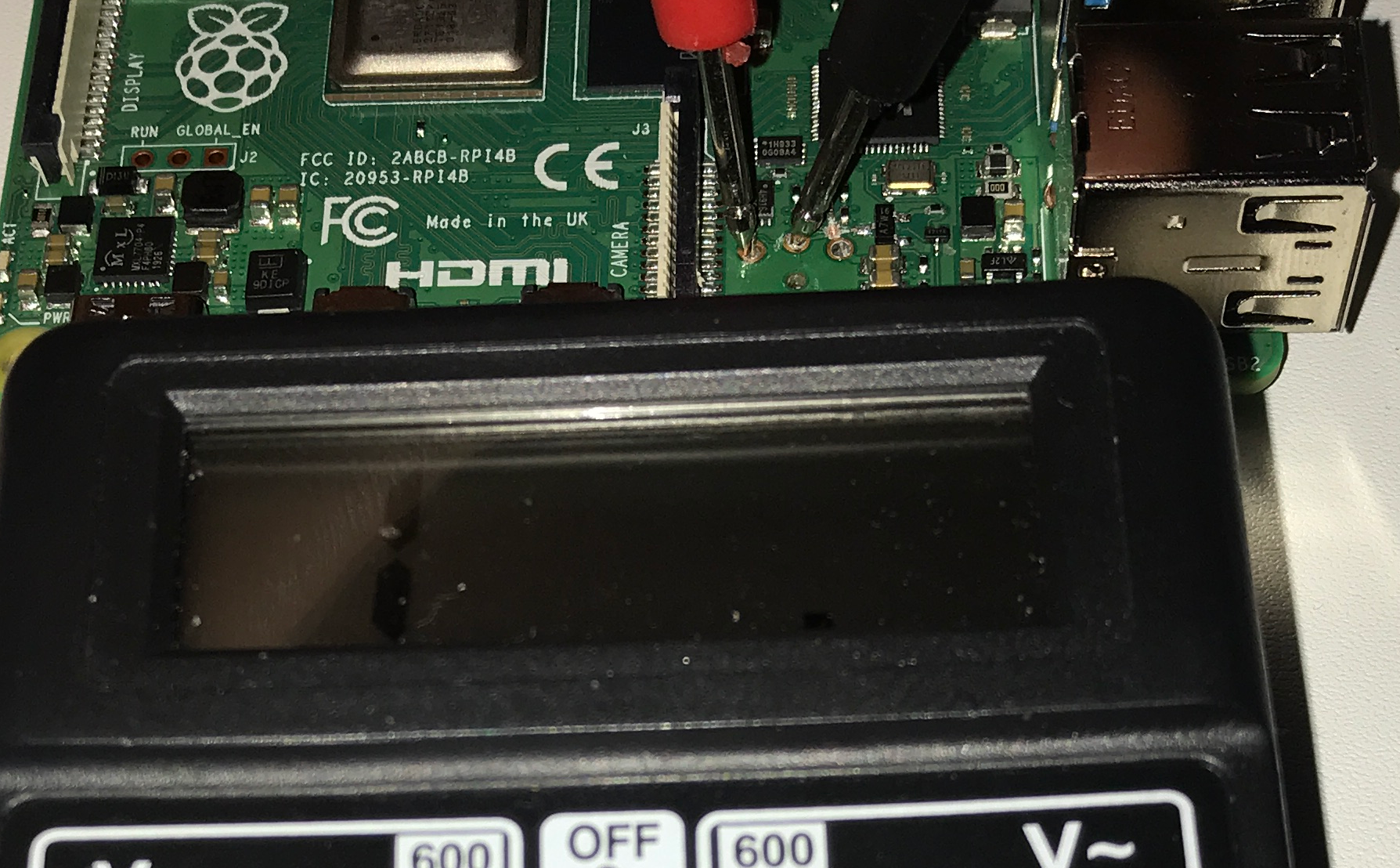
Testing current continuity between Sleeve and Ring2 on the RPi4 shows that it's already grounded with a 77 ohm of resistance, where it shows no continuity on the previous models of the Pi. Is this tied to a weird behavior of the BAV99 Signal Diode (D4)? or termination resistors?
Cutting the circuit between Sleeve and the D4 diode, didn't help:
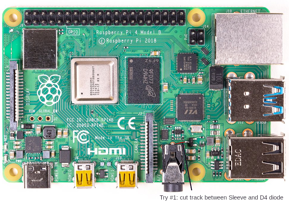
The resistance is still 77 ohm. This cut wasn't required.
Desoldering the Jack Socket to undercover hidden tracks and exclude the hypothesis of a defective socket:
The socket isn't involved in this resistance, however, there is an undocumented second track between Sleeve and a termination resistor, which didn't exist in previous models:
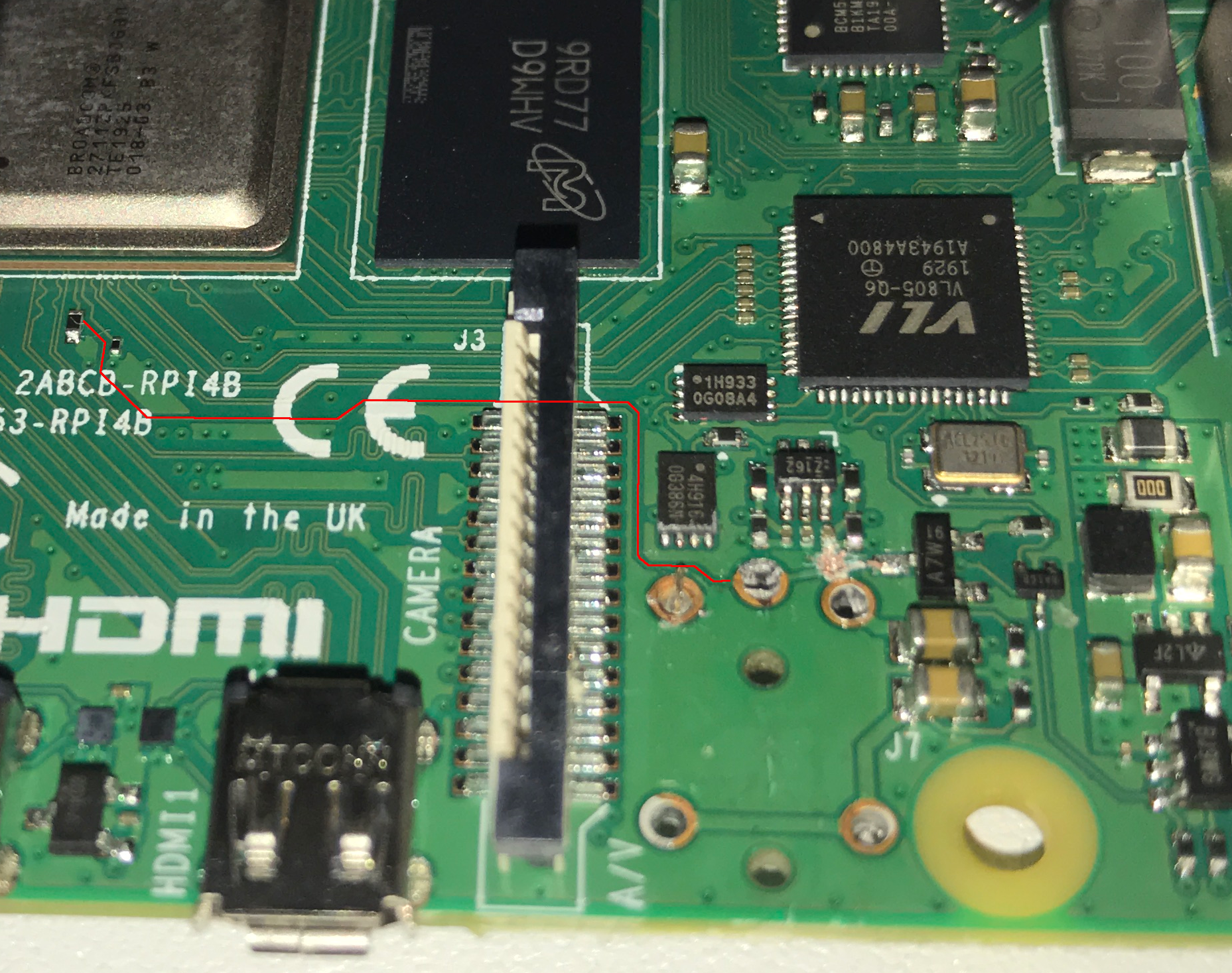
Cutting it down finally isolates Sleeve from ground:
Great, this did the job.
What about the software side so the push button can be detected to trigger the power on/off?
Shutdown script:
The shutdown script can leverage GPIO callbacks to reduce CPU resource consumption and trigger the shutdown routine only at GPIO change level (button pressed). Also, to prevent accidental power off, the script reads a second time the GPIO3 (Pin#5) value after 3 seconds to confirm that the power off button is still pressed.
#!/usr/bin/python
import time, subprocess

import RPi.GPIO as GPIO


GPIO.setmode(GPIO.BOARD)
GPIO.setwarnings(False)  # RuntimeWarning: A physical pull up resistor is fitted on this channel!
GPIO.setup(5, GPIO.IN, pull_up_down=GPIO.PUD_UP)

while True:
        GPIO.wait_for_edge(5, GPIO.FALLING)
        print("[*] Power off detected")
        time.sleep(3)
        ret = GPIO.input(5)
        if ret == 0:
                print("[*] Power of still pressed after 3 sec, shutting down")
                subprocess.call("shutdown -h now", shell=True, stdout=subprocess.PIPE, stderr=subprocess.PIPE)
        else:
                print("[*] Power of not pressed anymore. Skipping shutdown")
This one can be executed at boot time by either leveraging crontab or systemd. Example of a root crontab:
@reboot /root/scripts/shutdown.py
Conclusion:
In order to revive the Borkin power on/off button for the Raspberry Pi 4B, cutting the undocumented track between Sleeve and the termination resistor is required. This allows isolating it from ground. Then wiring the GPIO3 to the Sleeve pin as explained will do the trick.
One more thing: did the author implement the idea presented before?
Of course no, this is because:
- track between Sleeve and D4 diode was already cut for testing
- track between Sleeve and termination resistor was also cut for validation purposes
- the most important 2 pins from the Jack Socket (Sleeve and Ring2) were detroyed during the desoldering process
Author ended up performing:
- a dirty fix of the Jack Socket without soldering
- soldering a wire between GPIO3 (Pin#5) and the broken Sleeve on the Jack Socket
- soldering another wire between GND (Pin#6) and the broken Ring2 on the Jack Socket.
Open idea: in all Raspberry Pi models, leaving the COMPVID track between Sleeve and the D4 diode uncut does propably trigger a shutdown when it's active. This happens when the RPi is switched to composite video mode which can be done by pressing 3 (PAL) or 4 (NTSC) during NOOBS startup. Don't do it :)